 Thermal Energy Storage
Equipment Replacement:
Current Vogt HP / FTS / ATS equipment has been used to replace Avalanche Ice Harvesting systems and Ice Master Harvesting TES systems. In most cases, the existing storage tank can be retained. Vogt Thermal Energy Storage Equipment can be modified to utilize an existing tank and chilled water distribution system preventing costly system overhaul.
Upgrading In Place Equipment:
Existing HP and IGC equipment can be upgraded with an increase in efficiency and improvement in reliability.
Among the Areas of Upgrading:
- Flat bottom water pans – replace the ‘V’ notch pans and offer a more even flow of water onto the active area of the plates.
- Corrosion resistant defrost valves – Revised Thermal Expansion Valve piping lengthens life of the TEV and increases performance.
- Control system – allows for remote monitoring and control of your ice harvesting thermal storage system.
- Refrigerant changeover – with the phase out of R22, Vogt can recommend and facilitate requirements for upgrading your system.
- Plate upgrades – The HP system can now incorporate a deeper plate that can fit in the same frame. Capacity increases can be realized of up to 20% while extending the useful life of the unit.

Use: Use off peak or low load periods to build cooling reserves to be used for industrial or comfort cooling applications.
Solutions: Turbo HP / ATS / FTS product lines and Vogt Tube Ice TS series products.
Applications:
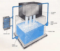
Unlike other thermal storage systems, the ice harvesting design uses an ice-making surface that is completely separate from the ice storage tank. The ice-making surface consists of stainless steel plates that are welded together to form computer-designed internal channels for controlled flow of refrigerant or stainless steel tubes integrated into a shell and tube heat exchanger. In the plate harvester, water is distributed uniformly over the outside of the plates. The plates are grouped vertically in modules directly above the ice storage tank. Ice forms on both sides in sheets 1/4″ inch thick. Then, at predetermined intervals, hot refrigerant enters the plates, causing the ice to break away and drop into the tank. The ice breaks into small pieces in the tank.
The Tube Ice design operates much the same way. Water is circulated to a tank above the stainless steel tubes and flows down each tube forming ice the length of the tube. At the optimal thickness, warm refrigerant enters the vessel and the ice releases from the tubes and drops into a storage tank. The harvest process causes the ice to break into much smaller pieces allowing for better heat transfer characteristics when the load occurs.
The cycles are repeated as long as there is need for additional cooling reserves. Fragmented ice gives a tremendous amount of heat transfer area, allowing very rapid melting with no risk of short circuiting of the return chilled water.
This continuous ice making capability is impossible with systems where heat transfer coils are submerged in ice storage tanks-because the ice making surfaces become encased in ice, insulating the heat transfer surface and reducing the efficiency of the system, while waiting for a thaw before production can resume.
Features:
- Infinite available surface area of ice for quick release of cooling to the load
-
The ice harvester acts as an efficient chiller when not making ice
-
The heat transfer surface and associated refrigerant piping is easy to access
-
Low temperature water (33 deg F) can be generated for economical water distribution (pumps, piping) to the cooling load.
Typical applications
-
Chemical processes requiring jacket cooling
-
Dehydration processes
-
Dairy- Pastuerization and blow molding processes
-
Clean room air conditioning
-
District Cooling (airports, hotels, business centers)
-
Inlet air cooling for combustion turbines


